Construction of an image of an object in a plane mirror. A
A mirror whose surface is a plane is called a flat mirror. Spherical and parabolic mirrors have a different surface shape. We will not study curved mirrors. In everyday life, flat mirrors are most often used, so we will focus on them.
When an object is in front of a mirror, it seems that there is the same object behind the mirror. What we see behind the mirror is called the image of the object.
Why do we see an object where it is not really there?
To answer this question, let's find out how an image appears in a flat mirror. Let there be some luminous point S in front of the mirror (Fig. 79). Of all the rays incident from this point on the mirror, we select for simplicity three rays: SO, SO 1 and SO 2. Each of these rays is reflected from the mirror according to the law of reflection of light, that is, at the same angle at which it falls on the mirror. After reflection, these rays enter the eye of the observer in a diverging beam. If we continue the reflected rays back, beyond the mirror, then they will converge at some point S 1 . This point is the image of the point S. It is here that the observer will see the light source.
The image S 1 is called imaginary, since it is obtained as a result of the intersection not of real rays of light, which are not behind the mirror, but of their imaginary extensions. (If this image were obtained as a point of intersection of real light rays, then it would be called real.)
So, the image in a flat mirror is always imaginary. Therefore, when you look in the mirror, you see in front of you not a real, but an imaginary image. Using the criteria for the equality of triangles (see Fig. 79), we can prove that S1O = OS. This means that the image in a flat mirror is at the same distance from it as the light source is in front of it.
Let's turn to experience. Place a piece of flat glass on the table. Glass reflects part of the light, and therefore glass can be used as a mirror. But since glass is transparent, we can see what is behind it at the same time. Let's put a lit candle in front of the glass (Fig. 80). Its imaginary image will appear behind the glass (if you place a piece of paper in the image of the flame, then, of course, it will not light up). 
Let's put on the other side of the glass (where we see the image) the same, but unlit candle and start moving it until it is aligned with the image obtained earlier (in this case, it will seem lit). Now let's measure the distance from the lit candle to the glass and from the glass to its image. These distances will be the same.
Experience also shows that the height of the candle image is equal to the height of the candle itself.
Summing up, we can say that the image of an object in a flat mirror is always: 1) imaginary; 2) straight, i.e. not inverted; 3) equal in size to the object itself; 4) located at the same distance behind the mirror as the object is located in front of it. In other words, the image of an object in a flat mirror is symmetrical to the object with respect to the plane of the mirror. 
Figure 81 shows the construction of an image in a flat mirror. Let the object look like an arrow AB. To build its image, you should:
1) lower the perpendicular from point A to the mirror and, extending it behind the mirror by exactly the same distance, mark point A 1 ;
2) lower the perpendicular from point B onto the mirror and, extending it behind the mirror by exactly the same distance, mark point B 1 ;
3) connect points A 1 and B 1 .
The resulting segment A 1 B 1 will be a virtual image of the arrow AB.
At first glance, there is no difference between an object and its image in a flat mirror. However, it is not. Look at the image of your right hand in the mirror. You will see that the fingers in this image are positioned as if this hand is left. This is not an accident: a mirror image always changes from right to left and vice versa.
Not everyone likes the difference between right and left. Some lovers of symmetry even try to write their literary works so that they are read the same way both from left to right and from right to left (such turnaround phrases are called palindromes), for example: “Throw ice to a zebra, beaver, loafer.”
It is interesting that animals react differently to their image in the mirror: some do not notice it, in others it causes obvious curiosity. It is of greatest interest to monkeys. When a large mirror was hung on the wall in one of the open enclosures for monkeys, all its inhabitants gathered around it. Monkeys did not leave the mirror, looking at their images, throughout the day. And only when their favorite treat was brought to them, the hungry animals went to the call of the worker. But, as one of the zoo observers later said, having taken a few steps from the mirror, they suddenly noticed how their new comrades from the “through the looking glass” were also leaving! The fear of not seeing them again turned out to be so high that the monkeys, refusing food, returned to the mirror. In the end, the mirror had to be removed.
Mirrors play an important role in human life, they are used both in everyday life and in technology.
Image acquisition using a flat mirror can be used, for example, in periscope(from the Greek "periscopeo" - I look around, I look around) - an optical device used for observations from tanks, submarines and various shelters (Fig. 82). 
A parallel beam of rays incident on a flat mirror remains parallel even after reflection (Fig. 83, a). It is this reflection that is called mirror reflection. But besides the specular reflection, there is also another type of reflection, when a parallel beam of rays incident on any surface, after reflection, is scattered by its microroughnesses in all possible directions (Fig. 83, b). Such a reflection is called diffuse, "it is created by non-smooth, rough and matte surfaces of bodies. It is thanks to the diffuse reflection of light that the objects around us become visible. 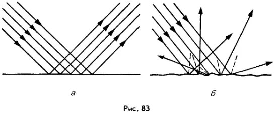
1. What is the difference between flat mirrors and spherical ones? 2. In what case is the image called imaginary? valid? 3. Describe the image in a flat mirror. 4. What is the difference between specular reflection and diffuse reflection? 5. What would we see around if all objects suddenly began to reflect light not diffusely, but specularly? 6. What is a periscope? How is it arranged? 7. Using Figure 79, prove that the image of a point in a flat mirror is at the same distance from the mirror as the given point is in front of it.
Experimental task. Stand at home in front of a mirror. Does the nature of the image you see match what is described in the textbook? On which side of your mirror double is the heart? Step back from the mirror one or two steps. What happened to the image? How has its distance from the mirror changed? Does this change the height of the image?
Construction of images in mirrors and their characteristics.
The image of any point A of an object in a spherical mirror can be constructed using any pair of standard rays: 2.6 - 2.9
2) the beam passing through the focus, after reflection, will go parallel to the optical axis on which this focus lies;
4) a beam incident on the pole of the mirror, after reflection from the mirror, goes symmetrically to the main optical axis (AB = VM)
Let's consider a few examples of building images in concave mirrors:
2) The object is located at a distance that is equal to the radius of curvature of the mirror. The image is real, equal in size to the size of the object, inverted, located strictly under the object (Fig. 2.11).
 Rice. 2.12 Rice. 2.12 |
3) The object is located between the focus and the pole of the mirror. Image - imaginary, enlarged, direct (Fig. 2.12)
Mirror Formula
Let's find the connection between the optical characteristic and the distances that determine the position of the object and its image.
Let the object be some point A located on the optical axis. Using the laws of light reflection, we will construct an image of this point (Fig. 2.13).

Let us denote the distance from the object to the pole of the mirror (AO), and from the pole to the image (OA¢).
Consider triangle APC, we get that
From the triangle APA¢, we get that ![]() . We exclude from these expressions the angle , since the only one that does not rely on OR.
. We exclude from these expressions the angle , since the only one that does not rely on OR.
, ![]() or
or
![]() (2.3)
(2.3)
The angles b, q, g are based on the OR. Let the beams under consideration be paraxial, then these angles are small and, therefore, their values in radian measure are equal to the tangent of these angles:
; ;  , where R=OC, is the radius of curvature of the mirror.
We substitute the obtained expressions into equation (2.3)


Since we found out earlier that the focal length is related to the radius of curvature of the mirror, then
 (2.4)
(2.4)
Expression (2.4) is called the mirror formula, which is used only with the sign rule:
Distances , , are considered positive if they are counted along the beam, and negative otherwise.
convex mirror.
Let's consider some examples on construction of images in convex mirrors.
2) The object is located at a distance equal to the radius of curvature. The image is imaginary, reduced, direct (Fig. 2.15)
The focus of a convex mirror is imaginary. Convex mirror formula
![]() .
.
The sign rule for d and f remains the same as for a concave mirror.
Linear magnification of an object is determined by the ratio of the height of the image to the height of the object itself.
![]() . (2.5)
. (2.5)
Thus, regardless of the location of the object relative to the convex mirror, the image is always imaginary, direct, reduced and located behind the mirror. While the images in a concave mirror are more diverse, they depend on the location of the object relative to the mirror. Therefore, concave mirrors are used more often.
Having considered the principles of imaging in various mirrors, we have come to understand the operation of such various instruments as astronomical telescopes and magnifying mirrors in cosmetic instruments and medical practice, we are able to design some of the instruments ourselves.
When constructing an image of any point of the source, there is no need to consider many rays. To do this, it is enough to build two beams; their intersection point will determine the location of the image. It is most convenient to construct those rays, the course of which is easy to follow. The path of these rays in the case of reflection from the mirror is shown in Fig. 213.
Rice. 213. Various techniques for constructing an image in a concave spherical mirror
Beam 1 passes through the center of the mirror and is therefore normal to the surface of the mirror. This beam returns after reflection exactly back along the secondary or main optical axis.
Beam 2 is parallel to the main optical axis of the mirror. This beam after reflection passes through the focus of the mirror.
Beam 3, which passes from the point of the object through the focus of the mirror. After reflection from the mirror, it goes parallel to the main optical axis.
Beam 4, incident on the mirror at its pole, will be reflected back symmetrically with respect to the main optical axis. To build an image, you can use any pair of these rays.
Having built images of a sufficient number of points of an extended object, one can get an idea of the position of the image of the entire object. In the case of a simple object shape shown in Fig. 213 (a line segment perpendicular to the main axis), it is enough to build only one point of the image. Some more complicated cases are considered in the exercises.
On fig. 210 were given geometric constructions of images for different positions of the object in front of the mirror. Rice. 210, in - the object is placed between the mirror and the focus - illustrates the construction of a virtual image by continuing the rays behind the mirror.

Rice. 214. Construction of an image in a convex spherical mirror.
On fig. 214 an example of constructing an image in a convex mirror is given. As mentioned earlier, in this case, virtual images are always obtained.
To build an image in a lens of any point of an object, as well as when building an image in a mirror, it is enough to find the intersection point of any two rays emanating from this point. The simplest construction is carried out using the rays shown in Fig. 215.

Rice. 215. Various techniques for constructing an image in a lens
Beam 1 goes along the secondary optical axis without changing direction.
Beam 2 falls on the lens parallel to the main optical axis; refracted, this beam passes through the back focus.
Beam 3 passes through the front focus; refracted, this beam goes parallel to the main optical axis.
The construction of these rays is carried out without any difficulty. Any other ray coming from the point would be much more difficult to construct - one would have to directly use the law of refraction. But this is not necessary, since after the construction is completed, any refracted ray will pass through the point .
It should be noted that when solving the problem of constructing an image of off-axis points, it is not at all necessary that the chosen simplest pairs of rays actually pass through the lens (or mirror). In many cases, for example, when photographing, the object is much larger than the lens, and rays 2 and 3 (Fig. 216) do not pass through the lens. However, these rays can be used to build an image. The real beam u involved in the formation of the image is limited by the frame of the lens (shaded cones), but converge, of course, at the same point , since it is proved that when refraction in the lens, the image of a point source is again a point.

Rice. 216. Building an image in the case when the object is much larger than the lens
Let us consider several typical cases of an image in a lens. We will consider the lens to be converging.
1. The object is from the lens, at a distance greater than twice the focal length. This is usually the position of the subject when photographing.

Rice. 217. Building an image in a lens when the object is behind double the focal length
The construction of the image is given in fig. 217. Since , then by the lens formula (89.6)
![]() ,
,
i.e., the image lies between the back focus and a thin lens located at twice the focal length from the optical center of the lens. The image is inverted (reverse) and reduced, since according to the magnification formula
2. We note an important special case when a beam of rays parallel to some side optical axis falls on the lens. A similar case occurs, for example, when photographing very distant extended objects. The construction of the image is given in fig. 218.
In this case, the image lies on the corresponding secondary optical axis, at the point of its intersection with the rear focal plane (the so-called plane perpendicular to the main axis and passing through the back focus of the lens).

Rice. 218. Image construction in the case when a beam of rays parallel to the side optical axis falls on the lens
The points of the focal plane are often called the foci of the corresponding side axes, leaving the name main focus behind the point corresponding to the main axis.
The focus distance from the main optical axis of the lens and the angle between the secondary axis under consideration and the main axis are obviously related by the formula (Fig. 218)
3. The subject lies between a point at twice the focal length and the front focus - the normal position of the subject when projected by a projection lamp. To study this case, it suffices to use the property of reversibility of the image in a lens. We will consider the source (see Fig. 217), then it will be an image. It is easy to see that in the case under consideration the image is inverse, enlarged and lies at a distance from the lens greater than twice the focal length.
It is useful to note the particular case when the object is at a distance equal to twice the focal length from the lens, i.e. . Then by the lens formula
![]() ,
,
i.e., the image also lies at twice the focal length from the lens. The image in this case is inverted. To increase, we find
i.e. the image has the same dimensions as the subject.
4. Of great importance is the special case when the source is in a plane perpendicular to the main axis of the lens and passing through the front focus.
This plane is also the focal plane; it is called the anterior focal plane. If a point source is located at any of the points of the focal plane, i.e., in one of the front foci, then a parallel beam of rays emerges from the lens, directed along the corresponding optical axis (Fig. 219). The angle between this axis and the main axis and the distance from the source to the axis are related by the formula
5. The subject lies between the front focus and the lens, i.e. . In this case, the image is direct and imaginary.
The construction of the image in this case is given in Fig. 220. Since , to increase we have
i.e. the image is enlarged. We will return to this case when considering the loop.

Rice. 219. Sources and lie in the front focal plane. (Beams of rays emerge from the lens parallel to the side axes passing through the source points)

Rice. 220. Building an image in the case when the object lies between the front focus and the lens
6. Building an image for a diverging lens (Fig. 221).
The image in a diverging lens is always imaginary and direct. Finally, since , the image is always reduced.

Rice. 221. Building an image in a diverging lens
Note that for all constructions of rays passing through a thin lens, we may not consider their path inside the lens itself. It is only important to know the location of the optical center and the main foci. Thus, a thin lens can be represented by a plane passing through the optical center perpendicular to the main optical axis, on which the positions of the main foci should be marked. This plane is called the principal plane. It is obvious that the beam entering the lens and leaving it passes through the same point of the main plane (Fig. 222, a). If we keep the outlines of the lens in the drawings, then only for a visual difference between the converging and diverging lenses; for all constructions, however, these outlines are superfluous. Sometimes, for greater simplicity of the drawing, instead of the outlines of the lens, a symbolic image is used, shown in Fig. 222b.

Rice. 222. a) Replacing the lens with the main plane; b) a symbolic image of a converging (left) and diverging (right) lens; c) replacement of the mirror by the main plane
Similarly, a spherical mirror can be represented by the main plane that touches the surface of the sphere at the pole of the mirror, indicating on the main axis the position of the center of the sphere and the main focus. The position indicates whether we are dealing with a concave (collecting) or a convex (diffusing) mirror (Fig. 222, c).
flat mirror is a flat surface that reflects light specularly.
The construction of an image in mirrors is based on the laws of rectilinear propagation and reflection of light.
Let's build an image of a point source S(Fig. 16.10). Light travels from the source in all directions. A beam of light falls on a mirror SAB, and the image is created by the entire beam. But to build an image, it is enough to take any two rays from this beam, for example SO And SC. Ray SO falls perpendicular to the surface of the mirror AB(the angle of incidence is 0), so the reflected will go in the opposite direction OS. Ray SC reflected at the angle \(~\gamma=\alpha\). reflected beams OS And SC diverge and do not intersect, but if they fall into the human eye, then the person will see the image S 1 which is the intersection point continuation reflected rays.
The image obtained at the intersection of reflected (or refracted) rays is called actual image.
The image obtained by crossing not the reflected (or refracted) rays themselves, but their continuations, is called imaginary image.
Thus, in a flat mirror, the image is always imaginary.
It can be proved (consider the triangles SOC and S 1 OC) that the distance SO= S 1 O, i.e. the image of the point S 1 is located at the same distance from the mirror as the point S itself. It follows that to construct the image of a point in a flat mirror, it is enough to lower the perpendicular from this point onto the flat mirror and continue it at the same distance beyond the mirror ( Fig. 16.11).

When constructing an image of an object, the latter is represented as a set of point light sources. Therefore, it is enough to find the image of the extreme points of the object.
The image A 1 B 1 (Fig. 16.12) of an object AB in a flat mirror is always imaginary, straight, of the same dimensions as the object, and symmetrical with respect to the mirror.
Any reflective surfaces in the course of school physics are usually called mirrors. Consider two geometric shapes of mirrors:
- flat
- spherical
- a reflective surface, the shape of which is a plane. The construction of an image in a flat mirror is based on , which, in the general case, can even be simplified (Fig. 1).

Rice. 1. Flat mirror
Let the source in our example be point A (point light source). Rays from a source propagate in all directions. To find the position of the image, it is enough to analyze the course of any two rays and find by construction the point of their intersection. The first beam (1) will be launched at any angle to the plane of the mirror, and, according to , its further movement will be at an angle of reflection equal to the angle of incidence. The second beam (2) can also be launched at any angle, but it is easier to draw it perpendicular to the surface, because, in this case, it will not experience refraction. The extensions of rays 1 and 2 converge at point B, in our case, this point is the point A (imaginary) (Fig. 1.1).
However, the triangles obtained in Figure 1.1 are the same (at two angles and a common side), then as a rule for constructing an image in a flat mirror, we can take: when constructing an image in a flat mirror, it is enough from source A to lower the perpendicular to the plane of the mirror, and then continue this perpendicular to the same length on the other side of the mirror(Fig. 1.2) .
Let's use this logic (Fig. 2).

Rice. 2. Examples of construction in a flat mirror
In the case of a non-point object, it is important to remember that the shape of the object in a flat mirror does not change. If we take into account that any object actually consists of points, then, in the general case, it is necessary to reflect each point. In a simplified version (for example, a segment or a simple figure), you can reflect the extreme points, and then connect them with straight lines (Fig. 3). In this case, AB is an object, A’B’ is an image.

Rice. 3. Construction of an object in a flat mirror
We have also introduced a new concept point light source is a source whose size can be neglected in our problem.
- a reflective surface, the shape of which is part of a sphere. The image search logic is the same - to find two rays coming from the source, the intersection of which (or their continuations) will give the desired image. In fact, for a spherical body there are three rather simple rays, the refraction of which can be easily predicted (Fig. 4). Let be a point source of light.

Rice. 4. Spherical mirror
First, let's introduce the characteristic line and points of the spherical mirror. Point 4 is called optical center of a spherical mirror. This point is the geometric center of the system. Line 5 - principal optical axis of a spherical mirror- a line passing through the optical center of a spherical mirror and perpendicular to the tangent to the mirror at this point. Dot F — focus of a spherical mirror, which has special properties (more on that later).
Then there are three ray paths that are simple enough to consider:
- blue. The beam passing through the focus, reflected from the mirror, passes parallel to the main optical axis (focus property),
- green. A beam incident on the main optical center of a spherical mirror is reflected at the same angle (),
- Red. A beam traveling parallel to the main optical axis, after refraction, passes through the focus (focus property).
We select any two rays and their intersection gives the image of our object ().
Focus- a conditional point on the main optical axis, at which the rays reflected from a spherical mirror converge parallel to the main optical axis.
For a spherical mirror focal length(distance from the optical center of the mirror to the focus) is a purely geometric concept, and this parameter can be found through the relationship:
Output: for mirrors, the most common ones are used. For a flat mirror, there is a simplification for imaging (Fig. 1.2). For spherical mirrors, there are three beam paths, any two of which give an image (Fig. 4).
Flat, spherical mirror updated: September 9, 2017 by: Ivan Ivanovich