Plot imaginary images. Building images that a thin lens gives. Thin Lens Formula
Point image S in the lens there will be a point of intersection of all refracted rays or their continuations. In the first case, the image is real, in the second - imaginary. As always, to find the intersection point of all rays, it is enough to construct any two. We can do this using the second law of refraction. To do this, you need to measure the angle of incidence of an arbitrary beam, calculate the angle of refraction, construct a refracted beam, which at some angle will fall on the other face of the lens. Having measured this angle of incidence, it is necessary to calculate the new angle of refraction and construct the outgoing beam. As you can see, the work is quite laborious, so it is usually avoided. According to the known properties of the lenses, three beams can be constructed without any calculations. A beam incident parallel to any optical axis, after double refraction, will pass through the real focus or its continuation will pass through the imaginary focus. According to the law of reversibility, a beam incident in the direction of the corresponding focus, after double refraction, will exit parallel to a certain optical axis. Finally, the beam will pass through the optical center of the lens without deviating.
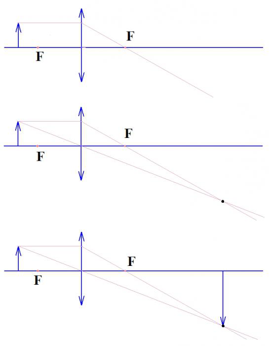
On fig. 7 plotted image point S in a converging lens, in Fig. 8 - in scattering. With such constructions, the main optical axis is depicted and the focal lengths F are shown on it (distances from the main foci or from the focal planes to the optical center of the lens) and double focal lengths (for converging lenses). Then they look for the intersection point of the refracted rays (or their continuations), using any two of the above.
Usually it is difficult to construct an image of a point located on the main optical axis. For such a construction, you need to take any beam that will be parallel to some side optical axis (dashed line in Fig. 9). After double refraction, it will pass through a secondary focus, which lies at the intersection of this secondary axis and the focal plane. As the second beam, it is convenient to use a beam that goes without refraction along the main optical axis.
Rice. 7 |
|
|
|

On fig. 10 shows two converging lenses. The second “better” collects the rays, brings them closer, it is “stronger”. optical power lens is called the reciprocal of the focal length:
The power of a lens is expressed in diopters (D).

Rice. 10
One diopter is the optical power of such a lens, the focal length of which is 1 m.
Converging lenses have a positive refractive power, while diverging lenses have a negative refractive power.
The construction of an image of an object in a converging lens is reduced to the construction of its extreme points. As an object, select an arrow AB(Fig. 11). Point Image A constructed as in Fig. 7, dot B1 can be found, as in Fig. 19. Let us introduce a notation (similar to those introduced when considering mirrors): the distance from the object to the lens | BO| = d; distance from object to image lens | BO 1 | = f, focal length | OF| = F. From the similarity of triangles A 1 B 1 O and ABO (along equal acute - vertical - angles right triangles similar). From the similarity of triangles A 1 B 1 F And DOF(by the same sign of similarity)  . Consequently,
Or fF = df − dF .
Dividing the equation term by term by dFf and moving the negative term to the other side of the equation, we get:
We have derived the lens formula similar to the mirror formula.
In the case of a diverging lens (Fig. 22), the near imaginary focus “works”. Note that point A1 is the point of intersection of the continuation of the refracted rays, and not the point of intersection of the refracted ray FD and the incident ray AO.
|
|


For proof, consider a beam incident from point A towards the far focus. After double refraction, it will exit the lens parallel to the main optical axis, so that its continuation will pass through the point A1. The image of point B can be constructed similarly to Fig. 9. From the similarity of the corresponding triangles;  ; fF = dF − df or
It is possible to conduct a study of the formula of a lens, similar to the study of the formula of a mirror.
How will the image of an object change if its half of the lens is broken? The image will become less intense, but neither its shape nor position will change. Similarly, the image of an object in any piece of a lens or mirror.
To construct an image of a point in an ideal system, it is sufficient to construct any two rays coming from this point. The intersection point of the outgoing rays corresponding to these two incident rays will be the desired image of this point.
Topics of the USE codifier: building images in lenses, formula thin lens.
The rules for the path of rays in thin lenses, formulated in , lead us to the most important statement.
Image theorem. If there is a luminous point in front of the lens, then after refraction in the lens, all rays (or their continuations) intersect at one point.
The point is called the point image.
If the refracted rays themselves intersect at a point, then the image is called valid. It can be obtained on the screen, since the energy of light rays is concentrated at a point.
If, however, not the refracted rays themselves intersect at a point, but their continuations (this happens when the refracted rays diverge after the lens), then the image is called imaginary. It cannot be received on the screen, because no energy is concentrated in the point. An imaginary image, we recall, arises due to the peculiarity of our brain - to complete the diverging rays until their imaginary intersection and see a luminous point in this intersection. An imaginary image exists only in our minds.
The image theorem serves as the basis for imaging in thin lenses. We will prove this theorem for both converging and diverging lenses.
Converging Lens: actual image points.
Let's look at a converging lens first. Let be the distance from the point to the lens, be the focal length of the lens. There are two fundamental different cases: and (as well as the intermediate case ). We will deal with these cases one by one; in each of them we
Let us discuss the properties of images of a point source and an extended object.
First case: . The point light source is located farther from the lens than the left focal plane (Fig. 1).
The beam passing through the optical center is not refracted. We will take arbitrary ray , we construct a point at which the refracted ray intersects with ray , and then we show that the position of the point does not depend on the choice of the ray (in other words, the point is the same for all possible rays ). Thus, it turns out that all rays emanating from the point intersect at the point after refraction in the lens, and the image theorem will be proved for the case under consideration.
We find the point by constructing further move beam . We can do this: we draw a side optical axis parallel to the beam until it intersects with the focal plane in the side focus, after which we draw the refracted beam until it intersects with the beam at the point.
Now we will look for the distance from the point to the lens. We will show that this distance is expressed only in terms of and , i.e., it is determined only by the position of the source and the properties of the lens, and thus does not depend on a particular beam.
Let us drop the perpendiculars and onto the main optical axis. Let's also draw it parallel to the main optical axis, that is, perpendicular to the lens. We get three pairs of similar triangles:
, (1)
, (2)
. (3)
As a result, we have the following chain of equalities (the number of the formula above the equal sign indicates from which pair of similar triangles this equality was obtained).
(4)
But , so relation (4) is rewritten as:
. (5)
From here we find the desired distance from the point to the lens:
. (6)
As we see, it really does not depend on the choice of the ray . Therefore, any ray after refraction in the lens will pass through the point constructed by us, and this point will be a real image of the source
The image theorem is proved in this case.
The practical importance of the image theorem is this. Since all the rays of the source intersect after the lens at one point - its image - then to build an image it is enough to take the two most convenient rays. What exactly?
If the source does not lie on the main optical axis, then the following are suitable as convenient beams:
The beam passing through the optical center of the lens - it is not refracted;
- a ray parallel to the main optical axis - after refraction, it goes through the focus.
The construction of an image using these rays is shown in Fig. 2.
If the point lies on the main optical axis, then only one convenient ray remains - running along the main optical axis. As the second beam, one has to take the "uncomfortable" one (Fig. 3).
Let's look again at the expression ( 5 ). It can be written in a slightly different form, more attractive and memorable. Let's first move the unit to the left:
We now divide both sides of this equality by a:
(7)
Relation (7) is called thin lens formula(or just the lens formula). So far, the lens formula has been obtained for the case of a converging lens and for . In what follows, we derive modifications of this formula for other cases.
Now let's return to relation (6) . Its importance is not limited to the fact that it proves the image theorem. We also see that it does not depend on the distance (Fig. 1, 2) between the source and the main optical axis!
This means that whatever point of the segment we take, its image will be at the same distance from the lens. It will lie on a segment - namely, at the intersection of the segment with a ray that will go through the lens without refraction. In particular, the image of a point will be a point .
Thus, we have established an important fact: the segment is puddles with the image of the segment. From now on, the original segment, the image of which we are interested in, we call subject and are marked with a red arrow in the figures. We need the direction of the arrow in order to follow whether the image is straight or inverted.
Converging lens: the actual image of an object.
Let's move on to the consideration of images of objects. Recall that while we are in the framework of the case . Three typical situations can be distinguished here.
one. . The image of the object is real, inverted, enlarged (Fig. 4; double focus is indicated). From the lens formula it follows that in this case it will be (why?).
Such a situation is realized, for example, in overhead projectors and film cameras - these optical devices give an enlarged image of what is on the film on the screen. If you have ever shown slides, then you know that the slide must be inserted into the projector upside down - so that the image on the screen looks right, and does not turn out upside down.
The ratio of the size of the image to the size of the object is called the linear magnification of the lens and is denoted by Г - (this is the capital Greek "gamma"):
From the similarity of triangles we get:
. (8)
Formula (8) is used in many problems where the linear magnification of the lens is involved.
2. . In this case, from formula (6) we find that and . The linear magnification of the lens according to (8) is equal to one, i.e. the size of the image is equal to the size of the object (Fig. 5).
 |
| Rice. 5.a=2f: image size is equal to the object size |
3. . In this case, it follows from the lens formula that (why?). The linear magnification of the lens will be less than one - the image is real, inverted, reduced (Fig. 6).
This situation is common for many optical instruments: cameras, binoculars, telescopes - in a word, those in which images of distant objects are obtained. As the object moves away from the lens, its image decreases in size and approaches the focal plane.
We have completely completed the consideration of the first case. Let's move on to the second case. It won't be as big anymore.
Converging lens: virtual image of a point.
Second case: . A point light source is located between the lens and the focal plane (Fig. 7).
Along with the ray going without refraction, we again consider an arbitrary ray. However, now two divergent beams and are obtained at the exit from the lens. Our eye will continue these rays until they intersect at a point.
The image theorem states that the point will be the same for all rays emanating from the point. We prove this again with three pairs of similar triangles:
Denoting again through the distance from to the lens, we have the corresponding chain of equalities (you can easily figure it out already):
. (9)
. (10)
The value does not depend on the ray, which proves the image theorem for our case. So, is a virtual image of the source . If the point does not lie on the main optical axis, then to construct an image, it is most convenient to take a beam passing through the optical center and a beam parallel to the main optical axis (Fig. 8).
Well, if the point lies on the main optical axis, then there is nowhere to go - you have to be content with a beam that falls obliquely on the lens (Fig. 9).
Relation (9) leads us to a variant of the lens formula for the considered case . First, we rewrite this relation as:
and then divide both sides of the resulting equality by a:
. (11)
Comparing (7) and (11) , we see a slight difference: the term is preceded by a plus sign if the image is real, and a minus sign if the image is imaginary.
The value calculated by formula (10) also does not depend on the distance between the point and the main optical axis. As above (remember the reasoning with a dot), this means that the image of the segment in Fig. 9 will be a segment.
Converging lens: a virtual image of an object.
With this in mind, we can easily build an image of an object located between the lens and the focal plane (Fig. 10). It turns out to be imaginary, direct and enlarged.
You see such an image when you look at a small object in a magnifying glass - a magnifying glass. The case is completely disassembled. As you can see, it is qualitatively different from our first case. This is not surprising - after all, between them lies an intermediate "catastrophic" case.
Converging lens: An object in the focal plane.
Intermediate case: The light source is located in the focal plane of the lens (Fig. 11).
As we remember from the previous section, the rays of a parallel beam, after refraction in a converging lens, will intersect in the focal plane - namely, at the main focus if the beam is incident perpendicular to the lens, and at the side focus if the beam is incident obliquely. Using the reversibility of the path of the rays, we conclude that all the rays of the source located in the focal plane, after leaving the lens, will go parallel to each other.
 |
| Rice. 11. a=f: no image |
Where is the image of the dot? There are no images. However, no one forbids us to assume that parallel rays intersect at an infinitely distant point. Then the image theorem remains valid in this case, the image is at infinity.
Accordingly, if the object is entirely located in the focal plane, the image of this object will be located at infinity(or, what is the same, will be absent).
So, we have completely considered the construction of images in a converging lens.
Converging lens: virtual image of a point.
Fortunately, there is not such a variety of situations as for a converging lens. The nature of the image does not depend on how far the object is from the diverging lens, so there will be only one case here.
Again we take a ray and an arbitrary ray (Fig. 12). At the exit from the lens, we have two divergent beams and , which our eye builds up to the intersection at the point .
We again have to prove the image theorem - that the point will be the same for all rays. We act with the help of the same three pairs of similar triangles:
(12)
. (13)
The value of b does not depend on the ray span
, so the extensions of all refracted rays span
intersect at a point - the imaginary image of the point . The image theorem is thus completely proved.
Recall that for a converging lens we obtained similar formulas (6) and (10) . In the case of their denominator vanished (the image went to infinity), and therefore this case distinguished fundamentally different situations and .
But for formula (13), the denominator does not vanish for any a. Therefore, for a diverging lens there is no qualitatively different situations source location - there is only one case here, as we said above.
If the point does not lie on the main optical axis, then two beams are convenient for constructing its image: one goes through the optical center, the other is parallel to the main optical axis (Fig. 13).
If the point lies on the main optical axis, then the second beam has to be taken arbitrary (Fig. 14).
To figure out which lens gives which image, you first need to remember that the main physical phenomenon that is used to create a lens is the one passing through the medium. It was this phenomenon that made it possible to create such a device that can control the direction of light fluxes. The principles of such control are explained to children at school, in the eighth grade physics course.
Definition of the word lens and the material used to make it
Lenses are used so that a person can see an enlarged or reduced image of an object. For example, using a telescope or microscope. Therefore, this device is transparent. This was done with the aim of seeing objects as we really are, only changed in size. It will not be colored, distorted, if this is not required. That is, the lens is a transparent body. Let's move on to its components. The lens consists of two surfaces. They can be curvilinear, often spherical, or one of them will be curvilinear and the other flat. It is from these planes that which lens gives which image depends. The material for the manufacture of lenses in wide everyday life are glass or plastic. Further we will talk specifically about glass lenses for a general understanding.
Division into convex and concave lenses
This division depends on the shape of the lens. If the lens has a middle wider than the edges, it is called convex. If, on the contrary, the middle is thinner than the edges, then such a device is called concave. What else is important? What matters is the environment in which the transparent body is located. After all, which lens gives which image depends on the refraction in two media - in the lens itself and in the matter surrounding it. Further, we will consider only air space, since lenses made of glass or plastic are higher than the established environmental indicator.
converging lens
Let's take a convex lens and pass a stream of light (parallel rays) through it. After passing through the plane of the surface, the flow is collected at one point, which is why the lens is called a converging lens.
To understand what kind of image a converging lens gives, and indeed any other, you need to remember its main parameters.
Important parameters for understanding the properties of a given glass body
If a lens is limited by two spherical surfaces, then its spheres, of course, have a certain radius. These radii are called the radii of curvature, which emerge from the centers of the spheres. The straight line that connects both centers is called the optical axis. A thin lens has a point through which the beam passes without much deviation from its previous direction. It is called the optical center of the lens. Through this center, perpendicular to the optical axis, one can draw perpendicular plane. It is called the main plane of the lens. There is also a point, which is called the main focus - the place where the rays will gather after passing through the glass body. When analyzing the question of what kind of image a converging lens gives, it is important to remember that its focus is with reverse side from the entry of rays. With a diverging lens, the focus is imaginary.

What image of an object does a converging lens give?
It directly depends on how far the object is placed relative to the lens. There will be no real image if an object is placed between the focus of the lens and the lens itself.

The image is imaginary, straight, and greatly enlarged. An elementary example of such an image is a magnifying glass.
If you place objects behind the focus, then two options are possible, but in both cases the image will be inverted and real in the first place. The difference is only in size. If you place objects between focus and double focus, the image is enlarged. If you place it behind the double focus, it will become reduced.

In some cases, it may happen that no image is received at all. As you can see from the figure above, if you place the object just at the focus of the lens, the lines that intersect to give the top point of the object run parallel. Accordingly, the intersection is out of the question, because the image can only be obtained somewhere in infinity. Also interesting is the case when an object is placed at the place of double focus. In this case, the image is turned upside down, real, but identical in size to the original object.
In the figures, this lens is schematically depicted as a segment with arrows at the ends pointing outward.
diverging lens
Logically, a concave lens is divergent. Its difference is that it gives a virtual image. Rays of light after passing it are scattered into different sides, so there is no actual image. The answer to the question of which image gives is always the same. In any case, the image will not be inverted, that is, straight, it will be imaginary and reduced.

In the figures, this lens is schematically depicted as a segment with arrows at the ends that look inward.
What is the principle of building an image
There are several building steps. The object whose image will be built has a vertex. Two lines must be drawn from it: one through the optical center of the lens, the other parallel to the optical axis to the lens, and then through the focus. The intersection of these lines will give the vertex of the image. All that is needed next is to connect the optical axis and the resulting point, parallel to the original object. In the case when the object is in front of the focus of the lens, the image will be imaginary and be on the same side as the object.
We remember what kind of image a diverging lens gives, so we are building an image for a concave lens, according to the same principle, with only one difference. The focus of the lens used for construction is on the same side as the object whose image needs to be built.

conclusions
Let's summarize the above materials in order to understand which lens gives which image. It is clear that the lens can increase and decrease, but the questions are different.
Question number one: which lenses produce a real image? The answer is only collective. It is a concave converging lens that can give a real image.
Question number two: what kind of lens produces a virtual image? The answer is scattering, and in some cases, when the object is between the focus and the lens, it is collective.
On fig. 22 shows the simplest profiles of glass lenses: plano-convex, biconvex (Fig. 22, b), flat-concave (Fig. 22, in) and biconcave (Fig. 22, G). The first two of them in the air are gathering lenses, and the second two - scattering. These names are associated with the fact that in a converging lens the beam, being refracted, deviates towards the optical axis, and vice versa in a diverging one.
Beams running parallel to the main optical axis are deflected behind a converging lens (Fig. 23, but) so that they gather at a point called focus. In a diverging lens, rays traveling parallel to the main optical axis are deflected so that their continuations are collected at the focus located on the side of the incident rays (Fig. 23, b). The distance to the foci on both sides of a thin lens is the same and does not depend on the profile of the right and left surfaces of the lens.
Rice. 22. Plano-convex ( but), biconvex ( b), plano-concave ( in) and biconcave ( G) lenses.

Rice. 23. The path of the rays running parallel to the main optical axis in the collecting (a) and diverging (b) lenses.
The beam passing through the center of the lens (Fig. 24, but- converging lens, fig. 24, b- diverging lens), is not refracted.
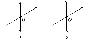
Rice. 24. The course of rays passing through the optical center ABOUT , in converging (a) and diverging (b) lenses.
Rays traveling parallel to each other, but not parallel to the main optical axis, intersect at a point (side focus) on focal plane, which passes through the focus of the lens perpendicular to the main optical axis (Fig. 25, but- converging lens, fig. 25, b- diverging lens).

Rice. 25. The course of parallel beams of rays in the collecting (a) and scattering (b) lenses.
![]() .
.
When constructing (Fig. 26) an image of a point (for example, the tip of an arrow) using a converging lens, two beams are emitted from this point: parallel to the main optical axis and through the center O lenses.

Rice. 26. Building images in a converging lens
Depending on the distance from the arrow to the lens, four types of images can be obtained, the characteristics of which are described in Table 2. When constructing an image of a segment perpendicular to the main optical axis, its image also turns out to be a segment perpendicular to the main optical axis.
When diverging lens an image of an object can only be of one type - imaginary, reduced, direct. This can be easily seen by carrying out similar constructions of the end of the arrow with the help of two rays (Fig. 27).
table 2
|
Distance
from the subject to the lens |
Characteristic Images |
|
0
< |
Imaginary, enlarged, direct |
|
|
